+86 13777722188


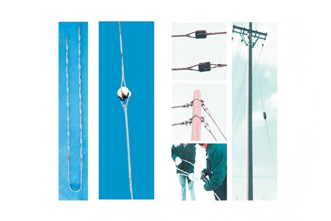
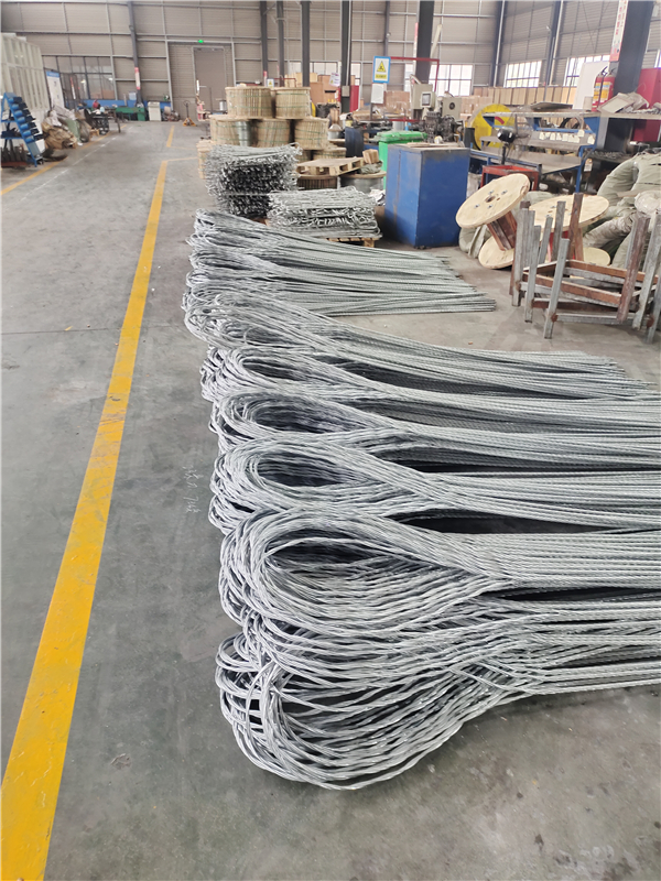
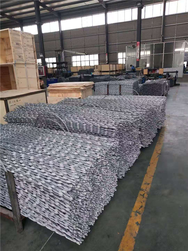
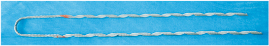
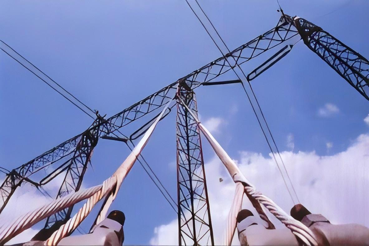
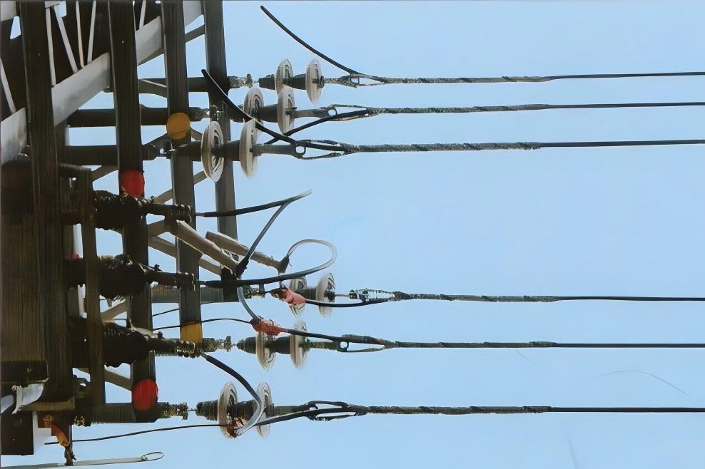
Preformed Tension Clamps (SNL)
Features
High Strength: Each conductor tension clamp has extra pre-twisted length, ensuring the pre-tension strength reaches over 95% of the conductor’s rated breaking force (CU/JS).
Uniform Stress Distribution: The clamp avoids damaging the conductor and distributes stress evenly, enhancing the conductor’s anti-vibration ability and extending its service life.
Excellent Corrosion Resistance: The material matches the conductor exactly, ensuring strong corrosion resistance.
Easy Installation: The clamp can be installed manually on-site quickly and easily, without special tools—one person can complete the process.
Guaranteed Installation Quality: Installation quality is easy to ensure, with high consistency. No special training is needed, and inspection can be done visually. The appearance is simple and elegant.
Strong Versatility: Compatible with various metals (see the installation manual for details).
Sufficient Gripping Force: The clamp has a firm twisted ring, providing enough gripping force for conductors like ACSR (aluminum conductor steel-reinforced), aluminum stranded wires, and aluminum alloy stranded wires. It also supports a wider range of conductor sizes.
Series Classification
Preformed Conductor Tension Clamps
Preformed Ground Wire Tension Clamps
Preformed Tension Clamps for Pull Lines
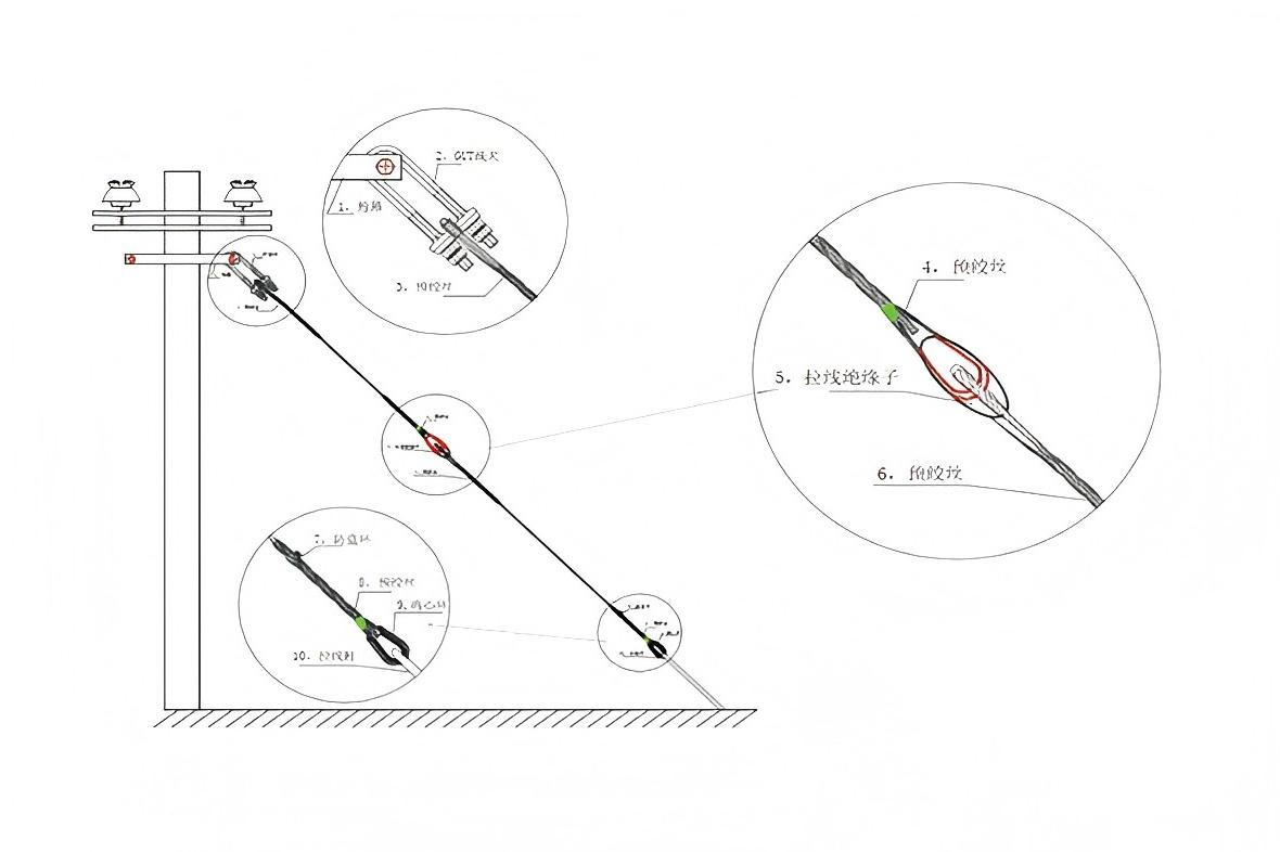
Component Description
1. Parts Explanation
① Semi-twisted loop: A standard design, suitable for small-diameter conductors.
Twisted loop: For larger-diameter conductors, twisted loops adapt to different hardware types.
② Installation mark (color code): Marks the starting point of installation and helps identify the clamp model.
③ Label: Diagram for Calculating Pulling Force
Materials
The clamps are manufactured from materials such as galvanized steel wires, aluminum-clad steel wires, aluminum alloy wires, and copper-clad steel wires.
Notes
The twist direction of SNL tension clamps (for ground wires/conductors) should be consistent. The standard SNL features a right - hand twist; if a left - hand twist is needed, please specify it in advance.
Due to the clamp’s special structure, each clamp can only be used once after bearing load and must not be reused.
When selecting or ordering products, the specification and model of the corresponding conductor must be provided.
HELIFORMED DEAD END CLAMP
Heliformed dead-ends, manufactured of aluminum covered steel or galvanized steel, is designed for single-pole distribution construction.
Mechanical strength meets the requirements of primaries, secondaries, and substation feeders.
Heliformed dead-end is recommended for direct application over plastic jacketed (not fabric covered) conductor.
Coated dead-ends are also recommended for jacketed conductor. The Heliformed dead-ends is designed to grip the conductor uniformly to prevent distortion of the conductor. It also offers a unique design that eliminates bolts, nuts, washers and other component parts that may become lost or damaged during installation or in service.
During installation, and at all times, care should be taken to avoid gouging or damaging the coating of the Heliformed dead-end or the conductor itself. Heliformed dead-ends should not be used as tools; for example come-alongs, puling-in grips, etc. Tools are not required nor recommended to install Heliformed dead-ends, except for hot stick applications.
Safety Considerations
This product is intended for a single (one-time) use and for the specified application
This product is intended for use by trained craftspeople only. This product should not be used by anyone who is not familiar with and trained in the use of it.
When working in the area of energized lines with this product, extra care should be taken to prevent accidental electrical contact.
For proper performance and personal safety be sure to select the proper size with preformed Armor Rods and clamps according the conductors size before application.
Dead ends are precision devices. To insure proper performance, they should be stored in cartons under cover and handled carefully.
The Dead ends are simple installation, except the need the screwdriver to seperate the conductor ends, usually needn't any other tools, just install by hand.
| catalogue number | Conductors GB/T1179-83 LGJ/LGJF | Section(mm²) | O.D(mm) | Length | Pieces |
| LNL-16/3 | 45658 | 45732 | 5.55 | 444 | 3 |
| LNL-25/4 | 45772 | 45772 | 6.86 | 546 | 3 |
| LNL-35/6 | 12936 | 12936 | 8.18 | 622 | 3 |
| LNL-50/8 | 18476 | 18476 | 9.6 | 685 | 3 |
| LNL-70/10 | 25842 | 25842 | 11.4 | 738 | 3 |
| LNL-95/15 | 95/15 | 95/15 | 13.61 | 876 | 4 |
| LNL-95/20 | 95/20 | 95/20 | 13.87 | 876 | 4 |
| LNL-120/7 | 120/7 | 120/7 | 14.5 | 876 | 4 |
| LNL-120/20 | 120/20 | 120/20 | 15.07 | 889 | 4 |
| LNL-120/25 | 120/25 | 120/25 | 15.74 | 889 | 4 |
| LNL-150/8 | 150/8 | 150/8 | 16 | 889 | 4 |
| LNL-150/20 | 150/20 | 150/20 | 16.87 | 1016 | 5 |
| LNL-150/25 | 150/28 | 150/28 | 17.1 | 1016 | 5 |
| LNL-150/35 | 150/35 | 150/35 | 17.6 | 1016 | 5 |
| LNL-185/10 | 185/10 | 185/10 | 18 | 1016 | 5 |
| LNL-185/25 | 185/25 | 185/25 | 18.88 | 1155 | 6 |
| LNL-185/30 | 185/30 | 185/30 | 19.9 | 1155 | 6 |
| LNL-185/45 | 185/45 | 185/45 | 19.6 | 1155 | 6 |
| LNL-210/10 | 210/10 | 210/10 | 19.6 | 1155 | 6 |
| LNL-210/25 | 210/25 | 210/25 | 19.98 | 1155 | 6 |
| LNL-210/35 | 210/35 | 210/35 | 20.88 | 1155 | 6 |
| LNL-210/50 | 210/50 | 210/50 | 20.38 | 1155 | 6 |
| LNL-240/30 | 240/30 | 240/30 | 21.6 | 1270 | 8 |
| LNL-240/40 | 240/40 | 240/40 | 21.66 | 1270 | 8 |
| LNL-300/15 | 300/15 | 300/15 | 23.04 | 1270 | 8 |
| LNL-300/20 | 300/20 | 300/20 | 23.43 | 1270 | 8 |
| LNL-300/25 | 300/25 | 300/25 | 23.76 | 1442 | 10 |
| LNL-300/40 | 300/40 | 300/40 | 26.94 | 1442 | 10 |
| LNL-300/50 | 300/50 | 300/50 | 24.26 | 1442 | 10 |
| catalogue number | conductor LJ GB/T1179-1983 | Length (mm) | color code | |
| Section(mm虏) | O.D(mm) | |||
| LNL-16/LJ | 16 | 4.62-5.16 | 406 | blue |
| LNL-25/LJ | 25 | 5.8-6.53 | 444 | orange |
| LNL-35/LJ | 35 | 7.35-8.26 | 622 | red |
| LNL-50/LJ | 50 | 8.27-9.25 | 685 | green |
| LNL-70/LJ | 70 | 10.4-11.28 | 736 | blue |
| LNL-95/LJ | 95 | 11.69-13.11 | 800 | orange |
| LNL-120/LJ | 120 | 13.12-14.66 | 876 | red |
| LNL-150/LJ | 150 | 14.67-16.59 | 889 | black |
| LNL-185/LJ | 185 | 16.6-18.77 | 1016 | green |
| LNL-210/LJ | 210 | 16.6-18.77 | 1016 | green |
| LNL-240/LJ | 240 | 18.78-21.26 | 1155 | orange |
| LNL-300/LJ | 300 | 21.27-24.05 | 1270 | blue |
| LNL-400/LJ | 400 | 24.06-27.2 | 1422 | brown |
| LNL-500/LJ | 500 | 27.21-30.78 | 1651 | orange |
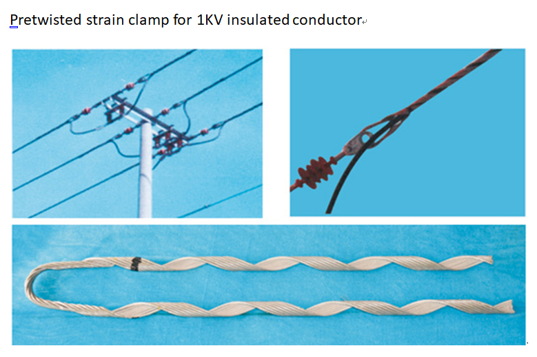
10kV Insulated Conductor Preformed Tension Clamp Selection Table
| Company product modal | Industry Sta ndard Model | Applicable Conductor Diameter Range (mm) | Applicable Conductor Model s for ≤1kV (GB12527-90) | Reference Length (mm) | Color Code | Optional Fittings | |
| Min | Max | ||||||
| LNL-10/JY-10KV | 10.4 | 11.68 | 10 | 740 | Blue | STC-05-B | |
| LNL-16/JY-10KV | 11.69 | 13.11 | 16 | 790 | Orange | ||
| LNL-25/JY-10KV | 13.12 | 14.66 | 25 | 860 | Purple | ||
| LNL-35/JY-10KV | NL-35/Jy | 14.67 | 16.59 | 35 | 690 | Blue | |
| LNL-50/JY-10KV | NL-50/Jy | 50 | 889 | ||||
| LNL-70/JY-10KV | NL-70/Jy | 16.60 | 18.77 | 70 | Red | ||
| LNL-95/JY-10KV | NL-95/Jy | 18.78 | 21.26 | 95 | 980 | Brown | |
| LNL-120/JY-10KV | NL-120/Jy | 120 | 980 | STC-07-B | |||
| LNL-150/JY-10KV | NL-150/Jy | 21.27 | 24.05 | 150 | Green | ||
| LNL-185/JY-10KV | NL-185/Jy | 24.06 | 27.20 | 185 | 1016 | Black | STC-10-B |
| LNL-240/JY-10KV | NL-240/Jy | 240 | |||||
| LNL-300/JY-10KV | NL-300/Jy | 27.21 | 30.78 | 300 | Purple | ||
High-quality conductive grease that is compatible with the wire.
③ It is allowed to make lap joints on the wire connecting strands. Before installing the lap joint clips, the wires must be thoroughly polished and coated with conductive grease. At the same time, the outer surface of the connecting strands must also be thoroughly polished to remove any possible oxide layer and adhesive. The lap joint area of the connecting strands also needs to be coated with conductive grease.
When the midpoint of the connecting strand is aligned with the damaged point on the wire during installation, the distance between the tail end of the connecting strand and the tail end of the already installed preformed wire guards or preformed short wire guards should not be less than 152 mm. This kind of connecting strand can only be used when the damaged point of the wire is at the support point or beyond the nearest damaged point, and the above-mentioned maintenance functions of the connecting strand can be exerted.
Preformed Ground Wire Tension Clamp Selection Table for Steel Strand
| Company product modal | Industry Sta ndard Model | Applicable Conductor Diameter Range (mm) | Applicable Conductor Types YB/T 5004-1993 (mm²) | Reference Clamp Length (mm) | Clamp Weight (kg) | Color Code | |
| LNL-25G | NL-25G | 6.60 | 25 | 635 | 0.22 | Yellow | |
| LNL-30G | 6.90 | 30 | 680 | 0.25 | Purple | ||
| LNL-35G | NL-35G | 7.80 | 35 | 711 | 0.30 | Black | |
| LNL-45G | 8.70 | 45 | 760 | 0.40 | Blue | ||
| LNL-50G | NL-50G | 9.00 | 50 | 901 | 0.53 | Orange | |
| LNL-55G | 9.60 | 55 | 920 | 0.55 | Red | ||
| LNL-60G | 10.00 | 60 | 950 | 0.65 | Purple | ||
| LNL-65G | 10.50 | 65 | 980 | 0.67 | Blue | ||
| LNL-70G | NL-70G | 11.00 | 70 | 1016 | 0.82 | Green | |
| LNL-80G | 11.40 | 80 | 1170 | 0.96 | Black | ||
| LNL-90G | 12.00 | 90 | 1180 | 1.30 | Red | ||
| LNL-95G | NL-95G | 12.50 | 95 | 1333 | 1.50 | Orange | |
| LNL-100G | NL-100G | 13.00 | 100 | 1333 | 1.50 | Yellow | |
| LNL-120G | NL-120G | 14.00 | 120 | 1460 | 2.22 | Yellow | |
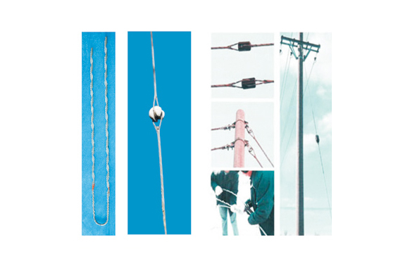
Pole Guy Wire Clamp(SDL)
| Serial Number | Product Specifications | Product Structure | Product Length (mm) | Color Code | |
| 1 | LDL-7/2.4 | 7/2.403 | 2290 | Black | |
| 2 | LDL-7/2.65 | 7/2.65 | 2290 | Brown | |
| 3 | LDL-7/2.92 | 7/2.92 | 2290 | Red | |
| 4 | LDL-7/3.25 | 7/3.25 | 2290 | Black | |
| 5 | LDL-7/3.27 | 7/3.27 | 2290 | Black | |
| 6 | LDL-7/3.35 | 7/3.35 | 2290 | Blue | |
| 7 | LDL-7/3.36 | 7/3.56 | 2290 | Brown | |
| 8 | LDL-7/4.0 | 7/4.0 | 2290 | Green | |
| 9 | LDL-19/2.65 | 19/2.65 | 2290 | Orange | |
| 10 | LDL-19/3.25 | 19/3.25 | 2290 | Brown | |
Preformed Guy Wire Tension Clamp Selection Table for Aluminum-Clad Steel Strand
| Company Product Model | Industry Standard Model | Applicable Conductor Diameter Range (mm) | Clamp Length (mm) | Color Code | |
| Minimum Outer Diameter | Maximum Outer Diameter | ||||
| LNL-0460LB | - | 4.42 | 4.6 | 420 | Orange |
| LNL-0585LB | - | 5.56 | 5.85 | 500 | Green |
| LNL-0600LB | - | 5.86 | 6.00 | 500 | Orange |
| LNL-0628LB | - | 6.01 | 6.28 | 520 | Yellow |
| LNL-0656LB | - | 6.29 | 6.56 | 520 | Black |
| LNL-0684LB | - | 6.57 | 6.84 | 540 | Red |
| LNL-0712LB | - | 6.85 | 7.12 | 570 | Blue |
| LNL-05740LB | - | 7.13 | 7.40 | 570 | Green |
| LNL-0767LB | - | 7.41 | 7.67 | 580 | Yellow |
| LNL-0795LB | - | 7.68 | 7.95 | 650 | Black |
| LNL-0823LB | - | 7.96 | 8.23 | 650 | Red |
| LNL-0854LB | - | 8.24 | 8.54 | 720 | Green |
| LNL-0869LB | - | 8.55 | 8.69 | 725 | Orange |
| LNL-05902LB | - | 8.70 | 9.02 | 775 | Yellow |
| LNL-0925LB | - | 9.03 | 9.25 | 770 | Blue |
| LNL-0963LB | - | 9.26 | 9.63 | 800 | Red |
| LNL-1001LB | - | 9.64 | 10.01 | 840 | Orange |
| LNL-1039LB | - | 10.02 | 10.39 | 850 | Yellow |
| LNL-1082LB | - | 10.40 | 10.82 | 900 | Black |
| LNL-1123LB | - | 10.83 | 11.23 | 940 | Green |
| LNL-1166LB | - | 11.24 | 11.66 | 950 | Yellow |
| LNL-1204LB | - | 11.67 | 12.04 | 980 | Red |
| LNL-1255LB | - | 12.05 | 12.55 | 1080 | Blue |
| LNL-1308LB | - | 12.56 | 13.08 | 1190 | Green |
| LNL-1361LB | 70/40 | 13.09 | 13.61 | 1220 | Red |
| LNL-1410LB | - | 13.62 | 14.10 | 1250 | Yellow |
| LNL-1448LB | - | 14.11 | 14.48 | 1270 | Blue |
| LNL-1501LB | - | 14.19 | 15.01 | 1270 | Orange |
| LNL-1554LB | - | 15.02 | 15.54 | 1370 | Green |
| LNL-1613LB | 95/55 | 15.55 | 16.13 | 1420 | Yellow |
| LNL-1679LB | - | 16.14 | 13.79 | 1500 | Black |
| LNL-10742LB | - | 16.80 | 17.42 | 1530 | Blue |
| LNL-1808LB | 120/7 | 17.43 | 18.08 | 1570 | Red |
| LNL-1882LB | - | 18.09 | 18.82 | Black | |
| LNL-1961LB | 18.83 | 19.61 | 1780 | Purple | |
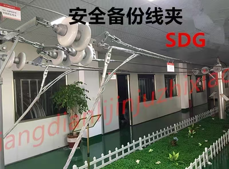
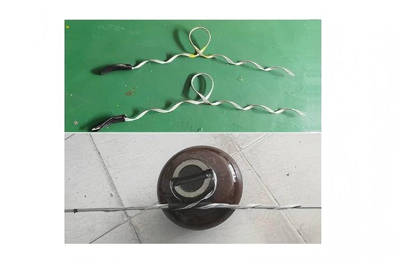
Preformed Safety Backup Clamp (SDG)
| Model | Cross-section (mm²) | Outer Diameter of Conductor (∅mm) | Length (mm) | Number of Strands | Weight (GK) | Remarks (Filler Strip) |
| LDG-9/20 | NL-50-900 | 7.8 | 900 | 5 | 0.76 | 7.8-800 |
| LDG-120/25 | NL-50-1100 | 9 | 880 | 5 | 0.76 | 9.0-800 |
| LDG-150/20 | NL-70-1400 | 10.8 | 1200 | 5 | 1.17 | 10.8-1050 |
| LDG-185/50 | NL-80-1300 | 11.8 | 1350 | 5 | 1.3 | 11.8-1150 |
| LDG-240/30 | NL-100-1600 | 13 | 1620 | 5 | 2.56 | 13.0-1500 |
| LDG-300/40 | NL-120-1800 | 14 | 1750 | 5 | 2.94 | 14.0-1600 |
| LDG-400/35 | NL-185-1900 | 17.5 | 1950 | 5 | 3.9 | 17.5-1720 |
| LDG-500/35 | NL-230-2180 | 19.6 | 2150 | 6 | 4.78 | 19.6-1900 |
| LDG-630/45 | NL-340-2670 | 24 | 2650 | 7 | 7.54 | 24.0-2400 |
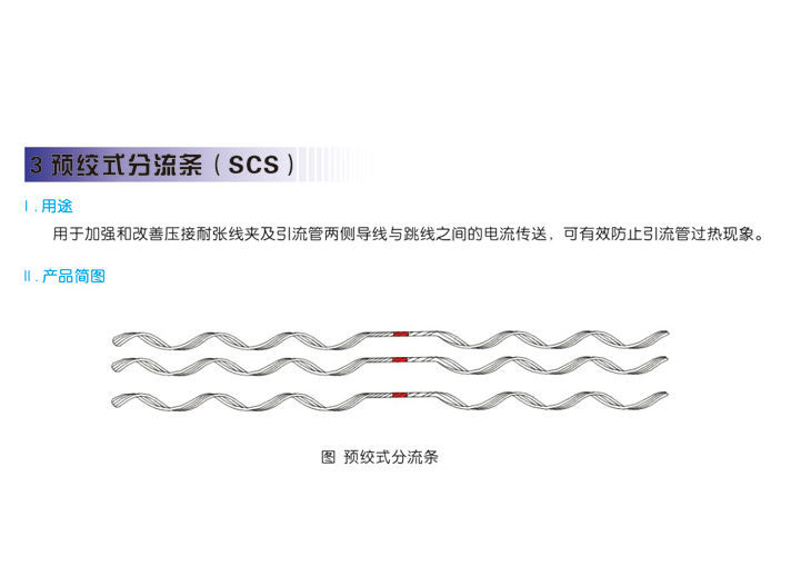
Safety Backup Clamp Current Shunt
| Model | Cross-section (mm²) | Outer Diameter of Conductor (mm) | Length (mm) | Number of Strands | Weight (GK) | Remarks |
| LDG-9/20 | CS-9/20 | Φ13.79–Φ14.1 | 1480 | 12 | 0.63 | 4–3 |
| LDG-120/25 | CS-120/25 | Φ15.42–Φ15.74 | 1550 | 12 | 0.82 | 4–3 |
| LDG-150/20 | CS-150/20 | Φ16.5–Φ17.0 | 1800 | 12 | 1.21 | 4–3 |
| LDG-185/30 | CS-185/30 | Φ18.59–Φ19.79 | 2000 | 12 | 1.81 | 4–3 |
| LDG-240/30 | CS-240/30 | Φ21.48–Φ22.09 | 2200 | 12 | 2.36 | 4–3 |
| LDG-300/40 | CS-300/40 | Φ23.6–Φ24.6 | 2600 | 12 | 3.82 | 4–3 |
| LDG-400/35 | CS-400/35 | Φ26.43–Φ27.29 | 2800 | 12 | 4.5 | 4–3 |
| LDG-500/35 | CS-500/35 | Φ30.00 | 2900 | 12 | 6.1 | 4–3 |
| LDG-630/45 | CS-630/45 | Φ33.60 | 3300 | 12 | 7.59 | 4–3 |
Safety Backup Clamp Reinforced Splice Strip
| Model | Cross-section (mm²) | Outer Diameter of Conductor (mm) | Length (mm) | Number of Strands | Weight (GK) | Remarks |
| LDG-9/20 | LS-9/20 | Φ13.79–Φ14.1 | 1900 | 12 | 0.83 | 4–3 |
| LDG-120/25 | LS-120/25 | Φ15.42–Φ15.74 | 2100 | 12 | 1.07 | 4–3 |
| LDG-150/20 | LS-150/20 | Φ16.5–Φ17.0 | 2500 | 12 | 1.65 | 4–3 |
| LDG-185/30 | LS-185/30 | Φ18.59–Φ19.79 | 2500 | 12 | 2.24 | 4–3 |
| LDG-240/30 | LS-240/30 | Φ21.48–Φ22.09 | 2900 | 12 | 3.06 | 4–3 |
| LDG-300/40 | LS-300/40 | Φ23.6–Φ24.6 | 3450 | 12 | 5.1 | 4–3 |
| LDG-400/35 | LS-400/35 | Φ26.43–Φ27.29 | 4000 | 12 | 6.5 | 4–3 |
| LDG-500/35 | LS-500/35 | Φ30.00 | 4450 | 12 | 9.4 | 4–3 |
| LDG-630/45 | LS-630/45 | Φ33.60 | 5500 | 12 | 12.65 | 4–3 |