+86 13777722188


Choosing the right Armoured Electrical Cable for a global project requires more than comparing conductor sizes and prices. It demands practical experience, careful engineering, and reliable evidence from approved manufacturers. A cable selected for a dry indoor plant may perform poorly in coastal soil, underground ducts, or areas with heavy mechanical traffic.
Project conditions should guide every decision. Review the operating voltage, current load, fault level, installation method, ambient temperature, and expected service life. Check whether steel wire, steel tape, or another armour design provides suitable mechanical protection. Consider moisture, chemicals, ultraviolet exposure, rodents, vibration, and fire performance. Small details matter. A sharp bend can damage armour. Poor gland selection can weaken an otherwise suitable cable system.
Global projects also involve different technical requirements. IEC, BS, UL, and regional specifications may not be interchangeable. Confirm the required certification, conductor material, insulation type, and testing records with qualified engineers and local authorities. Manufacturer data should clearly identify construction, ratings, test methods, and limitations. Independent inspection can add confidence, especially for critical power, infrastructure, and industrial installations.
Still, no checklist is perfect. Field conditions are often less predictable than drawings suggest. A cable may meet every stated rating yet fail because of poor storage, incorrect termination, or an underestimated installation route. Good selection therefore includes site surveys, realistic calculations, and documented quality control. This guide explains how to compare Armoured Electrical Cable options with a balanced view of performance, compliance, cost, and long-term reliability. Mistakes can happen. The goal is to reduce them before energisation.
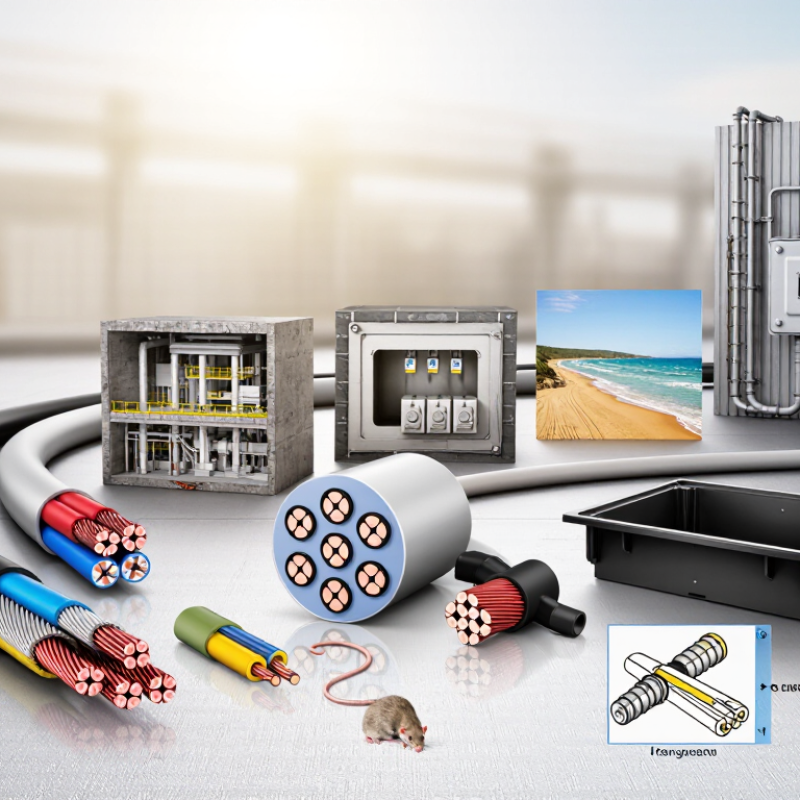
Armoured cable selection starts with the project environment, not a catalogue number. Voltage, current, route length, and installation method define the electrical design. A cable buried beneath a coastal road faces salt, moisture, crushing, and corrosion. Moisture changes everything. Soil chemistry also affects armour and sheath durability, especially where drainage is poor.
Mechanical risk deserves careful attention. Heavy vehicles, construction equipment, rodents, and sharp backfill can damage exposed systems. Select suitable armour based on expected impact, pulling tension, and bending requirements. Cable size must also consider ambient temperature, grouping, voltage drop, and short-circuit performance. Do not guess. Confirm these values through calculations and installation records. A neat calculation is not enough if the site conditions were estimated poorly.
Fire performance, smoke limits, earthing arrangements, and local electrical rules can vary between countries. Project teams should verify the required construction, test certificates, marking, and termination method before purchasing. Imported cable may meet one standard but fail a client’s specification or inspection process. That delay is avoidable. Check gland compatibility, drum dimensions, storage conditions, and delivery routes early. Field experience shows that damaged ends often result from careless handling, not cable design. Small details matter. Keep spare length for termination, protect open ends from water, and inspect every drum before installation. When conditions change during construction, review the selection instead of defending the original assumption.
Choosing armoured electrical cable for global projects starts with construction, not catalogue labels. During site inspections, I check the conductor, insulation, bedding, armour, and outer sheath as separate barriers. Copper offers high conductivity and stable terminations. Aluminium reduces weight, but joints need careful preparation. XLPE insulation tolerates higher operating temperatures than many PVC designs. The bedding must prevent armour from damaging the insulation. Small details matter. A rushed selection can fail before installation ends.
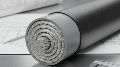
Protection levels depend on location and mechanical risk. Steel wire armour suits many fixed installations where impact or crushing is possible. Steel tape armour can provide useful protection, yet its performance differs under heavy mechanical stress. For corrosive soil or coastal air, choose a sheath tested for moisture, chemicals, and ultraviolet exposure. Fire performance also deserves attention in occupied buildings and evacuation routes. Confirm voltage rating, current capacity, earthing arrangement, and approved installation methods for each destination. Local rules may change the acceptable design. That is easy to underestimate.
Tips: Request construction drawings and test certificates, not only a product summary. Compare conductor size after considering temperature, grouping, and installation length. Check bending radius before ordering drums. Inspect sheath markings at delivery. Keep samples from each batch when traceability matters. I would also ask a local engineer to review the design; international assumptions are sometimes wrong. Leave room for correction.
Cable construction, conductor materials, and protection levels should be selected according to current capacity, voltage drop, installation environment, mechanical risk, and applicable IEC requirements.
Chart: Maximum conductor DC resistance at 20°C for common conductor sizes. Lower resistance generally means lower voltage drop and power loss for the same cable length and load. Values are representative IEC 60228 reference values for stranded Class 2 conductors and should be verified against the selected cable design and local installation standard.
Copper offers lower resistance for a given cross-sectional area. Aluminium can reduce weight and material cost but normally requires a larger cross-section and suitable termination hardware.
Galvanized steel wire armour is commonly selected for higher mechanical protection and tensile strength. Steel tape armour provides a protective barrier where the mechanical-duty requirement is lower.
For single-core AC cables, non-magnetic armour such as aluminium wire may be required to limit induced losses. Confirm the required IP rating, impact resistance, burial conditions, and fire performance.
Choosing armoured electrical cable starts with accurate electrical ratings, not cable appearance. Confirm the system voltage, operating current, fault level, and conductor temperature. Calculate voltage drop across the full route, especially for long feeders. A cable may carry normal load safely but fail during short-circuit conditions. Derating is essential when cables share trays, run in ducts, or cross hot areas. Check the applicable national and project standards before approval.
Installation methods change the cable’s performance. Cables installed underground need suitable bedding, mechanical protection, and controlled pulling tension. On trays, maintain the recommended spacing and bending radius. Use correctly sized glands at every termination. Bond the armour where required by the earthing design. Small errors matter. A gland that fits poorly can admit water or weaken the earth path. Site teams should inspect drums, record test results, and verify route conditions before installation.
Environmental demands often decide the final construction. Coastal projects may expose armour and joints to salt mist, while industrial sites can contain oil, solvents, or abrasive dust. Direct sunlight can raise sheath temperature beyond early calculations. Cold regions may make insulation less flexible during pulling. Consider moisture, flooding, fire exposure, rodents, and ultraviolet radiation together. A cable selected from a catalogue can still be wrong on site. Recheck assumptions against actual trench depth, ambient temperature, and installation access. The practical choice is sometimes less elegant, but more dependable.
How to Choose Armoured Electrical Cable for Global Projects?
International standards provide a reliable starting point, but they do not replace local compliance. For many low-voltage projects, IEC 60502-1 helps define cable construction and testing requirements. Additional standards may address flame spread, smoke emission, and corrosive gases. The correct choice depends on voltage, soil conditions, mechanical risk, and installation method.
A certificate alone can mislead. Check its scope, test voltage, conductor material, armour type, and production date. Confirm that the certificate covers the exact cable design, not a similar product. Local authorities may require specific markings, language, inspection records, or approved testing bodies. Import rules can also affect documentation. In practice, mismatched paperwork often delays delivery more than manufacturing problems. That lesson is easy to overlook.
Tips: Prepare a compliance matrix before purchasing. List international standards, national regulations, fire requirements, and inspection duties. Ask for complete test reports, declarations, and traceable batch information. Compare the cable’s rated temperature with the project’s actual conditions. Leave room for engineering review. No checklist is perfect. A local electrical consultant can identify requirements that overseas teams may miss, especially for underground routes, hazardous environments, or emergency systems. Recheck every assumption before shipment.
Choosing armoured electrical cable for global projects starts with supplier evidence, not catalogue claims. In field reviews, I check factory licenses, audited quality systems, traceability, and financial stability. The supplier should identify conductor material, insulation compound, armour type, and production location. I also request recent test reports from independent laboratories. A low price can still win the tender, but it may hide weaker documentation or longer replacement risks. The IEA’s Electricity Grids and Secure Energy Transitions report estimates annual grid investment must rise above USD 600 billion by 2030, compared with about USD 400 billion today. That pressure makes dependable procurement more important.
Testing must match the installation environment. IEC 60502-1 commonly supports low-voltage cable selection, while higher-voltage designs may require IEC 60840 or IEC 62067 testing. Verify conductor resistance against IEC 60228. Check flame propagation, smoke, and corrosive gases under the relevant IEC methods. For buried routes, review water penetration, crushing, impact, and bending performance. Factory routine tests are necessary, but independent witness testing adds confidence. It is not perfect.
The final cable specification should state voltage, conductor size, insulation, armour material, sheath, fire performance, drum length, and accepted tolerances. Include ambient temperature, soil thermal resistivity, installation depth, and fault-current duration. These details affect ampacity and short-circuit performance. Require serial-number traceability from drum to test certificate. Avoid accepting “equivalent” materials without written engineering review. The Global Energy Monitor reported more than 1,600 gigawatts of utility-scale solar and wind capacity under construction in 2023, increasing demand for reliable cable supply chains. Yet project schedules often reward speed too heavily. That deserves a second review.
| Project Stage | Evaluation Dimension | Recommended Requirement or Technical Check | Relevant Standard or Reference | Required Supplier Evidence | Decision Indicator |
|---|---|---|---|---|---|
| 1. Project Definition | Rated voltage | Confirm the cable voltage designation, such as 0.6/1 kV, against the system voltage, earthing arrangement, insulation level, and installation category. | IEC 60502-1; IEC 60183 | Approved datasheet, voltage designation, insulation material, and operating-temperature information. | Pass when fully aligned |
| 2. Project Definition | Conductor material and class | Specify copper or aluminium conductors and the required conductor class. Class 1 is solid; Class 2 is stranded for fixed installations; Class 5 is flexible. | IEC 60228 | Conductor construction, nominal cross-sectional area, DC resistance at 20 °C, and material declaration. | Pass when resistance complies |
| 3. Project Definition | Armour selection | Use galvanised steel wire armour or steel tape armour where mechanical protection is required. For single-core AC cables, confirm that the armour design avoids excessive magnetic effects; non-magnetic armour may be required. | IEC 60502-1; IEC 60364-5-52 | Armour material, wire or tape dimensions, coverage, corrosion-protection details, and single-core installation guidance. | Pass when installation-compatible |
| 4. Project Definition | Outer sheath environment | Select a sheath suitable for UV exposure, moisture, chemicals, oil, abrasion, burial, or indoor use. Do not assume a standard PVC sheath is suitable for every environment. | IEC 60502-1; project environmental specification | Sheath compound designation, temperature range, chemical-resistance data, UV or weathering test results where required. | Pass when risks are covered |
| 5. Supplier Evaluation | Manufacturing quality system | Evaluate documented control of incoming materials, conductor resistance, insulation and sheath extrusion, dimensional checks, marking, calibration, and nonconforming product. | ISO 9001 as a quality-management framework | Current certification scope, process-control plan, inspection records, calibration records, and corrective-action procedure. | Pass when records are traceable |
| 6. Supplier Evaluation | Material traceability | Require traceability from conductor, insulation, armour, and sheath materials to the finished cable drum and production batch. | Project quality plan; contractual requirements | Batch numbers, material certificates, production date, drum number, inspection plan, and certificate-of-conformity template. | Pass when batch linkage is complete |
| 7. Supplier Evaluation | Technical documentation | Check that the datasheet states conductor size, conductor class, insulation and sheath materials, armour type, approximate diameter, mass, bending radius, current ratings, and applicable standards. | IEC 60502-1; IEC 60228 | Controlled datasheet, dimensional drawing, installation instructions, and revision history. | Pass when data is complete |
| 8. Testing Plan | Routine electrical tests | Require routine tests appropriate to the cable design, including conductor resistance and voltage withstand or insulation checks specified by the applicable product standard. | IEC 60502-1 | Routine-test procedure, test voltage and duration, equipment calibration, results by drum, and authorized test report. | Pass when every drum is tested |
| 9. Testing Plan | Insulation and sheath integrity | Verify insulation thickness, sheath thickness, dimensional conformity, and absence of defects. Apply spark testing or other specified checks during production where required by the quality plan. | IEC 60502-1 | Dimensional inspection records, cross-sectional measurements, spark-test records, and visual-inspection results. | Pass when dimensions comply |
| 10. Testing Plan | Mechanical and ageing performance | For the selected compound and design, review tensile strength, elongation, ageing performance, and any required abrasion, oil, UV, or low-temperature testing. | IEC 60502-1; applicable material-test methods | Type-test reports identifying the tested cable construction, compound, dimensions, test laboratory, and acceptance criteria. | Pass when construction matches |
| 11. Testing Plan | Flame and smoke performance | Specify the required fire performance based on the installation location. Single-cable flame propagation, low smoke, and halogen-acid-gas requirements are separate properties and should not be treated as interchangeable. | IEC 60332-1-2; IEC 61034-2; IEC 60754-1 and IEC 60754-2 | Accredited test reports for the exact construction or an explicitly justified equivalent design. | Pass when all fire criteria match |
| 12. Testing Plan | Third-party inspection | For critical infrastructure or high-value orders, define witness points for raw-material inspection, in-process checks, final inspection, drum sealing, and document review. | Project inspection and test plan | Approved inspection and test plan, inspector qualifications, nonconformity log, release note, and final dossier index. | Pass when hold points are closed |
| 13. Final Specification | Electrical design | State the number of cores, nominal cross-sectional area, conductor material and class, rated voltage, insulation material, screen if required, armour, and sheath. | IEC 60228; IEC 60502-1 | Approved cable schedule and final technical datasheet with no conflicting values. | Pass when schedule is unambiguous |
| 14. Final Specification | Current-carrying capacity | Calculate ampacity using installation method, ambient or soil temperature, grouping, burial depth, thermal resistivity, and voltage-drop limits. Apply project derating factors. | IEC 60364-5-52; national installation rules where applicable | Calculation sheet showing assumptions, correction factors, short-circuit rating, and voltage-drop verification. | Pass when design margins are met |
| 15. Final Specification | Short-circuit withstand | Verify conductor and armour or metallic-screen short-circuit withstand for the specified fault current and clearing time. Confirm the permitted conductor operating temperature of the insulation system. | IEC 60949; IEC 60502-1 | Short-circuit calculation, fault-current basis, clearing time, and earthing or bonding arrangement. | Pass when thermal limits comply |
| 16. Final Specification | Installation and termination | Define minimum bending radius, pulling tension, gland type, lug compatibility, armour bonding, separation from other services, and termination requirements. | IEC 60502-1; IEC 60364-5-52; manufacturer installation instructions | Installation method statement, approved accessories, pulling calculation, bending-radius requirement, and termination drawings. | Pass when accessories are compatible |
| 17. Final Specification | Marking and packaging | Specify durable cable identification, sequential metre marking where required, core identification, drum dimensions, maximum drum mass, end sealing, and storage conditions. | IEC 60502-1; project packaging requirements | Marking artwork, drum drawing, packing list, cable-length certificate, and photographic release evidence. | Pass when identification is clear |
| 18. Final Approval | Document and change control | Approve one final cable construction and prohibit substitutions of conductor, insulation, armour, sheath, or manufacturing location without written technical approval. | Project quality plan; contract change-control procedure | Approved submittal, compliance matrix, deviation list, certificate package, and formal change-control record. | Pass when deviations are closed |