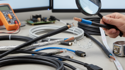
How to Choose the Right Insulated Cable?
Choosing the right Insulated Cable is a safety decision, not merely a purchasing decision. The cable must carry current reliably, resist heat, tolerate moisture, and fit the installation environment. A cable that looks suitable on a warehouse shelf may fail beside a hot motor, buried conduit, or coastal switchboard.
Industry forecasts show why this decision matters. The International Energy Agency’s Electricity Grids and Secure Energy Transitions report estimates that global grid investment must rise above USD 600 billion annually by 2030. It also projects that more than 80 million kilometres of grids may need to be added or replaced by 2040. These conditions increase demand for dependable, correctly specified cable systems. However, market growth does not make every product suitable.
This guide examines conductor material, insulation type, voltage rating, temperature limits, flexibility, fire performance, and installation conditions. Standards provide an essential foundation. IEC 60502-1 covers power cables with extruded insulation for rated voltages up to 1 kV, while IEC 60227 addresses PVC-insulated cables for lower-voltage applications. Always verify the applicable national requirements.
Real installations are less tidy than catalogues suggest. A cable may face sharp bends, vibration, sunlight, oil, or unexpected heat. Small details matter. Incorrect sizing can increase voltage drop and temperature rise. Choosing only by price is a common mistake. It is also tempting to trust a familiar brand without checking certification, test documentation, and traceability. That approach needs reconsideration. The best choice combines engineering calculations, manufacturer evidence, installation experience, and a clear understanding of future operating conditions.
What an Insulated Cable Is and How Its Construction Affects Performance
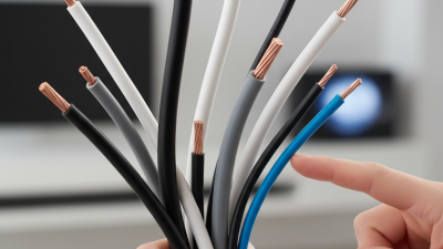
An insulated cable carries electrical current through a conductor protected by a nonconductive layer. That layer separates live metal from people, structures, and adjacent conductors. A cable may contain copper or aluminum cores, insulation, shielding, fillers, and an outer jacket. Every layer changes performance.
Conductor size controls resistance, heat generation, and voltage drop. A smaller conductor can overheat when the load exceeds its rated capacity. Insulation also matters. PVC handles many general applications, while cross-linked materials often tolerate higher temperatures. Rubber-like compounds can provide better flexibility in moving equipment. The outer jacket protects against moisture, abrasion, chemicals, and sunlight. However, one material rarely performs perfectly in every environment.
During cable selection, check the conductor area, voltage rating, temperature range, flexibility, and installation conditions. A cable installed inside a dry wall needs different protection from one exposed to rain, vibration, or repeated bending. Shielding may reduce electrical interference, but it can add weight and stiffness. I have seen projects choose a thicker cable simply because it looked safer. That choice increased cost and made installation difficult. A better assessment considers current, distance, ambient temperature, and local electrical standards. Cable markings should match certified test data, not only a supplier’s description. In uncertain installations, verification by a qualified electrician remains important.
How to Choose the Right Insulated Cable?
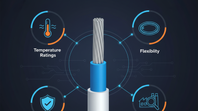
Cable insulation affects operating temperature, flexibility, chemical resistance, and service life. The chart shows typical continuous conductor temperature ratings for common insulation families. Actual limits depend on the applicable cable standard, installation conditions, conductor size, and formulation.
How to Select the Correct Cable Size, Voltage, and Current Rating
How to Choose the Right Insulated Cable?
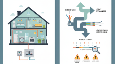
Cable selection starts with three numbers: conductor size, voltage rating, and current rating. The 2023 National Electrical Code, Table 310.16, shows that allowable ampacity changes with conductor material, insulation temperature, and installation conditions. A cable rated for 30 amps may carry less when surrounded by hot air or grouped with other circuits. IEC 60364-5-52 also requires designers to consider voltage drop, thermal limits, and installation methods. A larger cable is often safer, but not automatically correct.
For a 24-volt circuit carrying 10 amps, a 20-meter round trip can lose significant voltage. A five percent limit allows only 1.2 volts of loss. That means the circuit resistance should stay below 0.12 ohms. Small conductors may fail this test, even when their ampacity appears adequate. Check continuous load, starting current, ambient temperature, cable grouping, and insulation temperature. The cable’s voltage rating must meet or exceed the system voltage, including possible transients. In field inspections, voltage drop is often missed. I have found tidy installations that still performed poorly.
Tips: Measure the full cable route, not the room distance. Apply correction factors from the relevant standard. Verify terminal ratings before choosing insulation. Keep a record of assumptions. Some calculations look precise but depend on uncertain airflow, soil temperature, or future loading. Recheck them.
How to Choose the Right Insulated Cable? - How to Select the Correct Cable Size, Voltage, and Current Rating
| Conductor Cross-Section |
Approx. DC Resistance at 20°C
(Copper) |
Indicative Current Rating* |
Typical Insulation Voltage Rating |
Typical Applications |
Selection Notes |
| 1.5 mm² |
12.1 Ω/km |
14 A |
300/500 V or 450/750 V |
Lighting circuits and light-duty fixed wiring |
Use only when the calculated design current and installation conditions permit. |
| 2.5 mm² |
7.41 Ω/km |
20 A |
300/500 V or 450/750 V |
Socket circuits and general-purpose branch circuits |
A common size for moderate loads; verify protective-device coordination. |
| 4 mm² |
4.61 Ω/km |
26 A |
450/750 V |
Small heaters, kitchen equipment, and dedicated circuits |
Useful where the load is higher than a typical 2.5 mm² circuit can support. |
| 6 mm² |
3.08 Ω/km |
34 A |
450/750 V or 0.6/1 kV |
Electric water heaters, ovens, and medium-power feeders |
Check voltage drop carefully on long cable runs. |
| 10 mm² |
1.83 Ω/km |
46 A |
450/750 V or 0.6/1 kV |
Large single-phase loads and small distribution feeders |
Select a cable with sufficient short-circuit withstand for the installation. |
| 16 mm² |
1.15 Ω/km |
61 A |
0.6/1 kV |
Submain feeders and higher-power equipment |
Allow for grouping, ambient temperature, and cable-tray or conduit derating. |
| 25 mm² |
0.727 Ω/km |
80 A |
0.6/1 kV |
Distribution boards, machinery, and industrial feeders |
Confirm termination size, bending radius, and installation space. |
| 35 mm² |
0.524 Ω/km |
99 A |
0.6/1 kV |
Industrial submains and high-load distribution circuits |
Use a suitable cable lug and ensure the equipment terminals accept the conductor size. |
| 50 mm² |
0.387 Ω/km |
119 A |
0.6/1 kV |
Main feeders and large motor or transformer circuits |
Calculate prospective fault current and protective-device disconnection time. |
| 70 mm² |
0.268 Ω/km |
151 A |
0.6/1 kV |
High-capacity industrial and building distribution |
Parallel cables may be required for larger currents; apply matching and derating rules. |
| 95 mm² |
0.193 Ω/km |
182 A |
0.6/1 kV |
Large switchboard feeders and heavy industrial loads |
Professional design verification is required before installation. |
Important selection conditions: The current ratings are indicative values for copper conductors with 70°C PVC insulation, three loaded conductors, approximately 30°C ambient temperature, and a typical reference installation method. Actual ampacity depends on the applicable electrical code, conductor material, insulation temperature, installation method, ambient temperature, cable grouping, thermal insulation, and permissible voltage drop.
| Selection Step |
Recommended Check |
Basic Engineering Principle |
| 1. Determine load current |
Calculate the design current from the equipment power, system voltage, power factor, and efficiency. |
For single-phase AC: I = P ÷ (V × power factor × efficiency). |
| 2. Choose the voltage rating |
The cable voltage rating must be equal to or higher than the system voltage and suitable for the earthing arrangement. |
Common ratings include 300/500 V, 450/750 V, and 0.6/1 kV. |
| 3. Check ampacity |
Apply all correction factors for temperature, grouping, conduit, tray, burial, and thermal insulation. |
The corrected cable ampacity must be at least the design current. |
| 4. Verify voltage drop |
Calculate voltage drop over the complete circuit length, including the return conductor where applicable. |
A larger conductor may be necessary for long runs or sensitive equipment. |
| 5. Check protection and safety |
Coordinate the cable with the circuit breaker or fuse and verify short-circuit withstand, insulation temperature, and termination compatibility. |
Cable selection should comply with the electrical code applicable to the installation location. |
How to Verify Safety Standards, Installation Needs, and Long-Term Reliability
How to Choose the Right Insulated Cable?
Selecting an insulated cable starts with safety verification, not appearance. Check the voltage rating, conductor size, temperature range, and insulation type. A cable should match the circuit’s expected load, fault conditions, and surrounding environment. Look for recognized safety standards, such as IEC or equivalent national requirements. Do not trust a printed symbol alone. Confirm the certificate number through the testing organization’s public records. Review test reports for flame resistance, insulation performance, and mechanical strength. Paperwork matters.
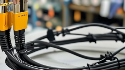
Installation conditions often expose weak choices. Measure the route before ordering cable. Consider bending radius, pulling tension, moisture, sunlight, chemicals, and heat near equipment. The cable must fit its glands, terminals, conduits, and protective devices. Leave enough length for clean termination, but avoid loose coils that trap heat. I once underestimated a tight bend near a panel. The cable installed, but the strain was obvious. That mistake deserved a redesign.
Long-term reliability depends on more than thick insulation. Ask about conductor material, batch traceability, aging tests, and storage requirements. Inspect the jacket for cracks, flattening, or uneven color before installation. After installation, test continuity and insulation resistance with suitable instruments. Record readings and revisit them during maintenance. A cable can pass today and still fail later. That is easy to forget. Clear records, trained installers, and scheduled inspections provide stronger evidence than confident assumptions.



 +86 13777722188
 WHATSAPP
 PHONE
PHONE E-MAIL