Leave Your Message

Why Choose Armoured Electrical Cable?

Why Choose Armoured Electrical Cable?

Modern power systems face harder conditions than clean laboratory tests suggest. Cables may run beneath concrete, across vibrating machinery, or beside sharp steel edges. Armoured Electrical Cable adds mechanical protection through steel wire, steel tape, or aluminium armour. That layer can reduce damage from impact, crushing, rodents, and accidental tool contact. It is not a magic shield.

The International Energy Agency’s Electricity 2024 report forecasts strong global electricity-demand growth through 2026. More generation, transport electrification, and industrial expansion will require dependable distribution networks. Grand View Research also identifies infrastructure development and renewable-energy projects as important drivers of cable demand. These trends explain the interest, but they do not remove the need for careful specification.

Electrical engineer John Cadick offers a useful reminder: “Safety is not an accident.” His point applies directly here. Armour cannot correct an incorrect voltage rating, poor gland selection, excessive bending, or careless termination. A cable may look solid while moisture enters through a damaged sheath. That small failure can become expensive.

The right choice depends on installation conditions, fault-current requirements, fire performance, earthing arrangements, and local standards. IEC 60364 and relevant national wiring rules provide important guidance. However, product data and installer experience still matter.

There is a less comfortable truth. Heavier cable is not automatically better. It may increase cost, weight, and installation difficulty. A properly designed Armoured Electrical Cable system balances protection, conductivity, flexibility, and service life. That balance deserves more attention than a simple “stronger is safer” assumption.
Why Choose Armoured Electrical Cable?

Define Armoured Cable Construction: IEC 60502-1 and 1 kV Ratings

Why Choose Armoured Electrical Cable?

Define Armoured Cable Construction: IEC 60502-1 and 1 kV Ratings

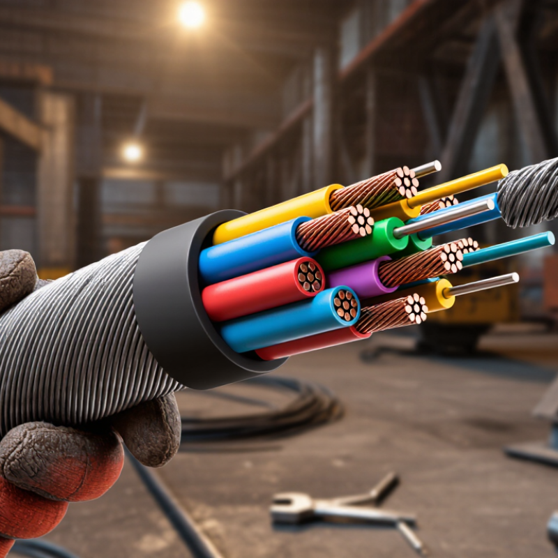
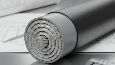
Armoured electrical cable is designed for fixed power installations where mechanical protection matters. Under IEC 60502-1, a typical cable includes a conductor, insulation, inner covering, metallic armour, and an outer sheath. Each layer has a practical purpose. The conductor carries current, while the insulation separates live parts from the surrounding structure. The inner covering holds the cable assembly firmly.

Protection matters.

For a common 0.6/1 kV cable, the rated voltage is 600 volts from conductor to earth and 1,000 volts between conductors. The standard also recognizes a maximum system voltage of 1.2 kV. Steel wire or steel tape armour can help resist impact, crushing, and installation stress. It may also provide an earth continuity path when correctly designed and bonded. The exact construction depends on conductor material, cable shape, installation method, and local requirements.

On real projects, installers should inspect the sheath for cuts, confirm bending limits, and check gland compatibility before termination. A cable can meet its voltage rating yet still be unsuitable for direct burial, wet locations, or severe chemical exposure. That is where specifications become important. Some decisions remain imperfect because site conditions change after design approval. Careful selection should therefore consider current capacity, fault protection, earthing, temperature, and mechanical loading together. IEC 60502-1 offers a technical framework, not a substitute for engineering judgment.

Compare Mechanical Protection: BS 5467 Steel-Tape and Wire-Armour Designs

Why Choose Armoured Electrical Cable?

When a cable runs beneath a loading bay, mechanical protection becomes more than a specification line. BS 5467 constructions can use steel tape or steel wire armour, depending on cable design and application. Steel tape forms a closely wrapped barrier around the insulated cores. It resists crushing and helps protect against accidental contact with tools or debris. It can also create a compact cable profile. Limits still matter. Tape armour is not automatically the strongest option for pulling tension.

Wire armour uses individual galvanized steel wires arranged around the bedding. These wires provide stronger longitudinal support during installation pulls. This matters on long routes, vertical drops, and exposed industrial runs. Wire spacing also allows practical bending, although the finished cable may feel heavier. During termination, the armour must be secured correctly. A loose gland connection can weaken earthing continuity and reduce mechanical protection. Small details matter. Where the design permits, the armour may also contribute to the protective conductor path.

Site conditions should decide the comparison. A shallow service route may favour tape armour where crushing risk dominates. A cable crossing a tray with repeated pulling forces may favour wire armour. That distinction is easy to miss. It is also imperfect, because installation method, conductor size, fault-current requirements, and gland selection change the result. Check the tested cable construction and installation instructions, rather than choosing by armour name alone. A clean-looking installation can still hide poor support.

Why Choose Armoured Electrical Cable? - Compare Mechanical Protection: BS 5467 Steel-Tape and Wire-Armour Designs

Comparison Dimension BS 5467 Steel-Tape Armour BS 5467 Wire Armour Practical Selection Note
Armour construction Overlapping steel tapes are applied helically around the cable assembly. Steel wires are laid helically around the cable, normally beneath the outer sheath. The armour type changes the cable’s mechanical behaviour, termination method, and installation requirements.
Primary mechanical strength Provides a continuous metallic layer with good general protection against radial impact and crushing. Provides strong longitudinal reinforcement as well as impact and crushing resistance. Wire armour is usually preferred where cable pulling forces or higher tensile loading are expected.
Protection against impact Good protection for fixed installations when the cable is correctly selected and supported. Very good protection, with the distributed wire layer helping resist local mechanical damage. For exposed routes or areas subject to handling and accidental contact, wire armour is often the more robust option.
Resistance to crushing Good resistance, particularly when the tape overlaps are maintained during manufacture and installation. Good to very good resistance; the result depends on wire diameter, lay, coverage, and cable diameter. Use the manufacturer’s declared crushing and impact limits for ducts, trenches, plant areas, and industrial routes.
Tensile performance during pulling Limited compared with wire armour; the conductors and inner layers should not be used as pulling members. Generally better suited to controlled pulling because the wire layer can provide greater longitudinal support. Pulling tension, sidewall pressure, bend radius, and installation equipment must still remain within the cable maker’s limits.
Flexibility and handling May be easier to form in some smaller fixed-installation designs, but the tape can resist repeated flexing. Often less flexible in larger sizes because of the heavier armour and increased overall stiffness. Neither design should be treated as a flexible cable unless the product is specifically rated for repeated movement.
Protection against rodents The metallic tape forms a substantial barrier against many types of rodent damage. Provides a strong metallic barrier; the effectiveness depends on armour coverage, sheath condition, and installation environment. For severe pest exposure, combine suitable armour with appropriate burial depth, ducting, or additional mechanical protection.
Earth continuity and bonding The metallic tape can form part of the protective conductor arrangement when the cable and accessories are designed and verified for that purpose. The wire armour commonly provides a useful low-impedance metallic path, subject to its cross-sectional area and applicable installation rules. Confirm armour current-carrying capacity, earth fault withstand, gland continuity, and bonding requirements through calculation.
Termination requirements Requires cable glands and accessories compatible with tape armour; careful preparation is needed to preserve armour continuity. Requires glands designed to grip and bond the armour wires securely while maintaining sheath sealing. Select glands, cleats, earth tags, and lugs for the actual armour type, cable diameter, enclosure rating, and environment.
Typical installation suitability Fixed indoor and outdoor routes where general mechanical protection is required and pulling loads are moderate. Fixed routes exposed to higher mechanical stress, longer pulls, industrial handling, or increased tensile demand. The installation method, available space, cable weight, and route geometry should guide the final choice.
Single-core considerations Ferromagnetic steel armour can cause additional heating and losses around single-core AC cables if the arrangement is unsuitable. Steel wire armour is generally associated with multicore cables; single-core AC applications commonly require non-magnetic armour or an alternative arrangement. Verify magnetic-effects calculations, trefoil or flat formation, cleat spacing, and the applicable wiring regulations.
Applicable cable rating context BS 5467 covers thermosetting-insulated armoured power cables for fixed installations, commonly including 600/1000 V designs. BS 5467 also covers relevant wire-armoured thermosetting-insulated cable constructions within its specified voltage and construction requirements. Always check the exact edition of the standard, cable construction, voltage rating, conductor material, sheath compound, and product certification.
Best general choice A practical option where continuous radial protection is needed and the route does not impose high pulling or tensile loads. A strong option where enhanced tensile support and robust mechanical protection are priorities. There is no universal winner; the correct design depends on fault protection, installation forces, environment, bending space, and compliance requirements.

Note: The comparisons above are general engineering guidance. Actual current ratings, minimum bending radii, tensile limits, armour resistance, short-circuit withstand, impact performance, and installation conditions must be taken from the applicable cable documentation and project regulations.

Calculate Ampacity and Voltage Drop Using IEC 60287 Methods

Why Choose Armoured Electrical Cable?

Calculate Ampacity and Voltage Drop Using IEC 60287 Methods

Armoured electrical cable suits demanding routes, but its rating cannot be guessed from conductor size. IEC 60287-1-1 calculates steady-state ampacity from conductor losses, insulation temperature, sheath currents, armour losses, and thermal resistance. The method reflects installation reality. A buried cable behaves differently from one fixed in a ventilated tray.

For example, an engineer might assess a three-core cable at 50 Hz, with a 90°C conductor limit, 30°C soil temperature, 0.6 metre burial depth, and 1.5 K·m/W soil thermal resistivity. IEC 60287 then combines AC conductor resistance with thermal resistances around the cable. Armour bonding also matters. Poor bonding assumptions can distort the result.

Voltage drop needs a separate check. A practical three-phase expression is ΔV ≈ √3I(Rcosφ + Xsinφ)L . Resistance must reflect conductor operating temperature, not only the catalogue value. Reactance changes with spacing, armour arrangement, and installation geometry.

The IEA Electricity 2024 report forecasts global electricity demand to grow by 3.4% annually through 2026, increasing pressure on reliable distribution planning. CIGRE guidance also stresses site-specific thermal conditions for cable systems.

A neat spreadsheet can still be wrong. Soil data may be missing. Load diversity may be overstated. Engineers should record assumptions, test sensitivity, and verify the final design against local installation conditions.

Match Site Hazards to IEC 60364 Installation and Earthing Requirements

Why Choose Armoured Electrical Cable?

Choosing armoured electrical cable starts with the site hazard, not cable appearance. Construction areas may expose cables to vehicle movement, sharp edges, moisture, or buried pressure. Armour can provide mechanical protection, but it is not a complete safety solution. The installation still requires correct sizing, routing, glands, and termination methods. A cable that looks strong may still fail under excessive current or poor fault protection.

IEC 60364 requires designers to assess protection against electric shock, external influences, and automatic disconnection. Under IEC 60364-4-41, the protective measure must disconnect supply within the required time. IEC 60364-5-52 addresses cable selection and installation conditions. IEC 60364-5-54 covers earthing arrangements and protective conductors. The armour may serve as a protective conductor only when its continuity, cross-sectional area, and fault-current capacity are verified. Never assume it qualifies automatically.

Check the earthing arrangement. TN, TT, and IT systems create different protection requirements. In a TT installation, an earth electrode and residual protection may be essential. In a TN system, the armour connection must support a reliable fault path back to the source. Test continuity before energising. Inspect every gland. A loose termination can leave the armour electrically useless. Field conditions also change; a cable route beside a crane may need more protection than the original drawing suggests. I have seen designs rely too heavily on standard tables, while actual soil, temperature, and grouping conditions were overlooked. Recheck the details.

Why Choose Armoured Electrical Cable?

Matching site hazards to IEC 60364 installation and earthing requirements helps determine whether mechanical protection, a protective conductor, or both are needed. The chart shows the minimum protective-conductor cross-sectional area commonly derived from IEC 60364-5-54 Table 54.3 for conductors made from the same material.

For a phase conductor up to 16 mm², the protective conductor is sized at the same cross-sectional area. Between 16 and 35 mm², 16 mm² is used; above 35 mm², the protective conductor is sized at half the phase-conductor area. Cable armour must not be assumed to provide the required protective function unless its electrical continuity, fault-current withstand, termination, and local installation rules have been verified.

Verify Fire Performance and Thermal Limits: IEC 60331, 60332, 90°C XLPE

Armoured electrical cable deserves attention when fire survival and heat limits affect life safety.

IEC 60331 tests whether a cable maintains circuit integrity during defined fire exposure. The exact temperature, duration, and mechanical shock depend on the applicable test part and edition. Passing IEC 60331 does not guarantee performance in every tunnel, plant, or building. Installation spacing matters.

IEC 60332 addresses flame propagation, not continued circuit operation. A cable may resist flame spread yet lose power quickly. That difference is often missed.

NFPA’s Home Structure Fires report, published in 2022, estimated about 32,000 U.S. home fires annually involved electrical distribution and lighting equipment during 2016–2020. The figure supports a practical concern: cable selection cannot rely on voltage rating alone.

Armouring can improve mechanical protection and provide a dependable bonding path, but it does not automatically create fire resistance.

XLPE insulation commonly carries a 90°C maximum conductor operating temperature under specified conditions, referenced in cable standards such as IEC 60502-1. This is not the surrounding air temperature. Ambient heat, grouping, soil conditions, installation depth, and emergency loading reduce usable capacity.

Engineers should verify current-carrying capacity with manufacturer-independent calculation methods and local rules. A 90°C label can mislead. Short-circuit limits also require separate checking, because XLPE’s temporary thermal capability is higher than its continuous rating.

In practice, a cable that passes the fire test may still be thermally undersized. That uncomfortable gap deserves review.